The Ulterra QUEST is available as a freshwater motor and can be controlled with a foot pedal, Advanced GPS Micro Remote, and Advanced GPS Remote. All Ulterra QUEST motors come with Advanced GPS installed.
Jump to:
- Installation Considerations
- Deploy with the Foot Pedal
- Trim with the Foot Pedal
- Stow with the Foot Pedal
- Deploy with the Advanced GPS Navigation Wireless Remote
- Trim with the Advanced GPS Navigation Wireless Remote
- Stow with the Advanced GPS Navigation Wireless Remote
- Deploy with the One-Boat Network App
- Trim with the One-Boat Network App
- Stow with the One-Boat Network App
- Stow from the Indicator Panel
- Foot Pedal
- Advanced GPS Navigation Wireless Remote Functions
- Advanced GPS Navigation Micro Remote Functions
- Adjust the Lift Belt
- Emergency Stow the Ulterra QUEST
- Cold Weather Auto Stow, Deploy, and Trim Trolling Motor Care Tips
- Installing an External Transducer on an Ulterra QUEST (2023-present)
- Manuals
Ulterra QUEST Installation Considerations
When installing the Ulterra QUEST, we recommend following the instructions in the Ulterra QUEST Installation Guide. We also recommend a 60 amp circuit breaker. You may also want to consider using a Trolling Motor Plug as it will allow you to easily disconnect your motor from power when not in use or when charging the trolling motor batteries.
- It is recommended that the motor be mounted as close to the centerline of the boat as possible.
- Make sure the area under the mounting location is clear to drill holes and install nuts and washers.
- Make sure the motor rest is positioned far enough beyond the edge of the boat.
- The motor must not encounter any obstructions as it is lowered into the water or raised into the boat when stowed and deployed.
-
When installing the Ulterra QUEST, we recommend following the instructions
in the Ulterra QUEST Installation Guide. We also recommend a 60 amp circuit
breaker
Click here for MKR-27 60 Amp Circuit Breaker purchase options. -
Consider a quick release or adapter bracket with the installation of
your motor. The button below will walk you through selecting the best
Quick Release Bracket for your boat and motor.
-
You may also want to consider using a Trolling Motor Plug as it will
allow you to easily disconnect your motor from power when not in use
or when charging the trolling motor batteries.
Click here for MKR-28 Trolling Motor Plug purchase options.
Ulterra QUEST Dimensions
Mount Dimensions
Deployed Position Dimensions
Stowed Position Dimensions
Foot Pedal Dimension
Deploy with the Foot Pedal
- Locate the Indicator Panel at the base of the Mount.
- Make sure that the motor is on by checking that the green LED above the System Ready Indicator is on.
- On the Foot Pedal, press the Mode Button until the amber LED in the center of the Indicator Panel on the Foot Pedal is illuminated. This puts the Foot Pedal in Ulterra Mode.
- To deploy the motor when it is stowed, double press the Stow/Deploy button.
Trim with the Foot Pedal
Once the boat is on the water, it may be necessary to adjust the trim of the lower unit up or down to achieve an optimum depth for motor performance. When setting the depth of the motor, be sure the top of the motor is submerged at least 12" below the surface of the water to avoid churning or agitation of surface water. There will be times when you will need to move your motor up or down depending on how your boat is responding. You can trim up to avoid hitting underwater objects and you can trim down if your prop is coming out of the water.
When trimming the motor using the Foot Pedal, the motor is programmed to operate safely and limit prop rotation when it is within certain limits. The prop will temporarily stop while trimming the motor and resume once trimming is stopped. Trim limits are in place to avoid damage to the unit. An upper trim limit is set 12" from the bottom of the mount to the center of the lower unit. A lower trim limit is set approximately 1.5" from the bottom of the control head to the trim housing. A prop lockout region, defined as 14" from the bottom of mount to the center of the lower unit, is used to eliminate the possibility of the motor contacting the boat hull. All functions, with the exception of manual steer and track record, are canceled upon trimming into this region.
- To trim the motor up, press the Trim Up button located on the bottom left of the Foot Pedal.
- To trim the motor down, press the Trim Down button located on the bottom right of the Foot Pedal.
Stow with the Foot Pedal
- Locate the Indicator Panel at the base of the Mount.
- Make sure that the motor is on by checking that the green LED above the System Ready Indicator is on.
- On the Foot Pedal, press the Mode Button until the amber LED in the center of the Indicator Panel on the Foot Pedal is illuminated. This puts the Foot Pedal in Ulterra Mode.
- To stow the motor when it is deployed, press the Stow/Deploy button.
Note* - If your motor is stalling at a 45-degree angle when attempting to stow, this indicates that batteries are too low to fully stow the motor. If this occurs, re-engage power, deploy the motor, trim the motor to its highest setting, and turn power off until batteries can be recharged. Once batteries are charged, attempt to stow the motor again
Deploy with the Advanced GPS Navigation Wireless Remote
- Press the Power button.
- Use the Speed Up or Speed Down button to find the motor name, either Instinct or Ulterra.
- Press the Steer Right button to select Instinct or Ulterra.
- Press the Steer Right button to select Deploy.
- The Instinct/Ulterra motor will deploy. While the Motor is deploying, it is possible to pause the action. To pause the action, press the Steer Right button to select Pause.
- To resume the Deploy action, press the Steer Right button to select Deploy.
- If the Motor continues, it will complete the deploy process and normal motor operation will follow.
Trim with the Advanced GPS Navigation Wireless Remote
- Make sure that the motor is deployed, and then press the Power button.
- Use the Speed Up or Speed Down button to find Instinct/Ulterra. Use the Steer Right button to select it.
- Once in the Instinct/Ulterra Menu, use the Speed Up or Speed Down button to select Trim Up or Trim Down. Trimming up will raise the motor and trimming down will lower the motor.
- Press and hold the Steer Right button to select it.
- When the motor has reached its highest trim limit, the Prop will be locked out and the Trim Up option will be disabled. The Prop will stay locked out even when the Deployment Menu has closed. Trim the motor down and out of the Prop Lockout zone to restore functionality.
- When the lower trim limit is reached, the Trim Down option will be disabled.
Stow with the Advanced GPS Navigation Wireless Remote
- Press the Power button.
- Use the Speed Up or Speed Down button to find Instinct. Use the Steer Right button to select it.
- Use the Speed Up or Speed Down button to find Stow. Use the Steer Right button to select it.
- The motor will stow. While the Motor is stowing, it is possible to pause the action. To pause the action, press the Speed Down button to find Pause and press the Steer Right button to select it.
- To resume the Stow action, press the Steer Right button to select Stow.
- If the Motor continues, it will complete the Stow process and normal motor operation will follow.
Deploy with the One-Boat Network App
- Open the OBN app on the mobile device.
- From the OBN home screen, tap on the Motor menu.
- Before the Motor app home screen will open, select Agree on the on-screen prompt.
- Tap Trim/Stow on the bottom of the screen to open the Trim/Stow/Deploy menu.
- Tap Deploy to automatically deploy the motor. Normal motor operation will follow.
Trim with the One-Boat Network App
Once the boat is on the water, it may be necessary to adjust the trim of the lower unit up or down to achieve an optimum depth for motor performance. When setting the depth of the motor, be sure the top of the motor is submerged at least 12" below the surface of the water to avoid churning or agitation of surface water. There will be times when you will need to move your motor up or down depending on how your boat is responding. You can trim up to avoid hitting underwater objects and you can trim down if your prop is coming out of the water.
When trimming the motor using the One-Boat Network app, the motor is programmed to operate safely and limit prop rotation when it is within certain limits. The prop will temporarily stop while trimming the motor and resume once trimming is stopped. Trim limits are in place to avoid damage to the unit. An upper trim limit is set 12" from the bottom of the mount to the center of the lower unit. A lower trim limit is set approximately 1.5" from the bottom of the control head to the trim housing. A prop lockout region, defined as 14" from the bottom of mount to the center of the lower unit, is used to eliminate the possibility of the motor contacting the boat hull. All functions, with the exception of manual steer and track record, are canceled upon trimming into the Prop Lockout Region.
- Open the Motor menu on the OBN app.
- Tap Trim/Stow on the bottom of the screen to open the Trim/Stow/Deploy menu.
- To trim the motor up, press and hold Trim Up . Continue to hold until the lower unit is at the desired height.
- To trim the motor down, press and hold Trim Down . Continue to hold until the lower unit as at the desired height.
Stow with the One-Boat Network App
- Open the OBN app on the mobile device.
- From the OBN home screen, tap on the Motor menu.
- Before the Motor app home screen will open, select Agree on the on-screen prompt.
- Tap Trim/Stow on the bottom of the screen to open the Trim/Stow/Deploy menu.
- Tap Stow to automatically stow the motor. The Prop will be disabled and "Motor Stowed" will display on the screen.
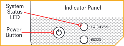
Stow from the Indicator Panel
In the unlikely event that your foot pedal, wireless remote or One-Boat Network app becomes non-functioning, you can stow from the base of the motor.
*NOTE- The motor cannot be deployed from the Indicator Panel. You can only deploy using the foot pedal, the Advanced GPS Navigation Wireless Remote, the One-Boat Network App, or a connected Humminbird.
- Locate the Indicator Panel at the base of the Mount.
- Make sure that the motor is on by checking that the green LED next to the System Ready Indicator is on.
- Press and hold the Power Button located on the Indicator Panel for ten seconds.
- The red and green LEDs next to the Status (red) and System Ready (green) Indicators will flash alternately, and the motor will begin to stow.
Foot Pedal
The controls on the Foot Pedal are easy to use. It features Dual mode operation controls AutoStow/Deploy and Power Trim as well as steering, speed, prop on/off, Spot-Lock and a One-Boat Network programmable button. It includes an 18' cord with waterproof connector. The trolling motor can also be controlled by an Advanced GPS Navigation Wireless Remote, as well as any Bluetooth or Advanced GPS Navigation Micro Remote. Please refer to the associated remote manual for respective instructions.
Foot Pedal Modes
The Foot Pedal has two modes of operation, Normal Mode and Deployment Mode. To alternate between the Modes, press the MODE button located on the right side of the Foot Pedal, just above the Speed Control Knob. The MODE LED on the Indicator Panel illuminates white when Deployment Mode is engaged. The Indicator Panel is located on the top-left side of the Foot Pedal. Switching between Modes affects the functionality of the three buttons at the bottom of the Foot Pedal. These buttons include:
-
Normal Mode
When in Normal Mode, the buttons at the bottom of the Foot Pedal function to Steer Left, Steer Right, and turn the Prop ON/OFF. The white MODE LED on the Indicator Panel will not be illuminated when in Normal Mode -
Deployment Mode
When in Deployment Mode, the buttons at the bottom of the Foot Pedal function to Trim Up, Trim Down, and Stow/Deploy. The white MODE LED on the Indicator Panel will be illuminated during Deployment Mode.
Foot Pedal Operation
Motor Speed
The Speed Control Knob is located between the MODE and Spot-Lock buttons on the right side of the Foot Pedal.
- Turn the Speed Control Knob forward to increase speed and backward to decrease speed.
- The Speed Control Knob can be set in a range from 0 to 10 and can be adjusted in both Normal and Deployment Modes.
- Speed can also be adjusted using a remote.
Stow/Deploy
The Stow/Deploy button is located in the middle, at the bottom of the Foot Pedal. It functions to stow and deploy the motor when the Foot Pedal is operating in Deployment Mode.
- The white MODE LED on the Indicator Panel will be illuminated during Deployment Mode.
- When the trolling motor is deployed, press the Stow/Deploy button to stow it.
- Double-press the Stow/Deploy button on the Foot Pedal to deploy the motor when it is stowed.
- When stowing and deploying the motor, it automatically disables the operational function of the Foot Pedal or paired remote. The Prop is also disabled when the motor is stowed and deployed.
Trim Down/Trim Up
The Trim Down and Trim Up buttons are located at the bottom of the Foot Pedal. The Trim Down button trims the motor down, and the Trim Up button trims the motor up. The buttons trim the motor when the Foot Pedal operates in Deployment Mode.
- The white MODE LED on the Indicator Panel will be illuminated during Deployment Mode.
Prop ON/OFF
The Prop ON/OFF button is located in the middle, at the bottom of the Foot Pedal. It functions to turn the Prop on and off when the Foot Pedal is operating in Normal Mode.
- The white MODE LED on the Indicator Panel will not be illuminated when in Normal Mode.
- The Prop will turn on when pressure is applied and off when the pressure on the button is removed.
- The Prop button does not change the behavior of the Prop when the Constant button is engaged.
Constant
The Constant button is located on the left side of the Foot Pedal, towards the bottom, directly below the One-Boat Network button. It functions to toggle the motor between Constant motor operation and Momentary motor operation.
- The green CONSTANT LED on the Indicator Panel will be illuminated when the motor is in Constant motor operation.
- In Constant motor operation, the Prop will continually run, regardless of whether or not pressure is being applied to the Momentary button or Prop ON/OFF button.
- While in Constant motor operation, the Prop will run continuously at the speed set by the Speed Control Knob, the Advanced GPS Navigation Wireless Remote, or the One-Boat Network app.
- If the Prop encounters an obstruction while in Momentary or Constant motor operation while running, the increased electrical current generated by the obstruction will signal the motor to decrease the power to the Prop to prevent damage. If the current overload is detected for more than 20 seconds, the Prop will be disabled to prevent damage to the motor. In this event, the operator can turn the Prop back on after clearing the obstruction.
Momentary
In Momentary motor operation, the Prop will only run while downward pressure is applied to the Momentary button. The Momentary button is on the Toe End of the Heel/Toe pedal.
- Applying downward pressure to the Momentary button will turn the prop on. The motor will run at the speed set by the Speed Control Knob, the Advanced GPS Navigation Wireless Remote, or the One-Boat Network app.
- Removing pressure from the Momentary button will turn the prop off. No indicator light is associated with the Momentary button.
- The Momentary button functions similarly to the Prop ON/OFF button.
Heel/Toe Steering
Push the Toe End of the Foot Pedal down to turn right, and push the Heel End of the Foot Pedal down to turn left. The position and direction of the Control Head directly correspond to the position of the motor.
- Use the foot on the Foot Pedal to control the steering direction during manual operation.
- The direction of the trolling motor can also be controlled with the Advanced GPS Navigation Wireless Remote and the One-Boat Network app
Steer Right/Steer Left
The Steer Right and Steer Left buttons are located at the bottom of the Foot Pedal. They function to steer the trolling motor to the right and left when the Foot Pedal is operating in Normal Mode.
- The white MODE LED on the Indicator Panel will not be illuminated when in Normal Mode.
- Holding the Steer Right or Steer Left buttons down will continue to steer the motor to the left or right.
- Small steering changes of less than one degree can be made by quickly tapping the Steer Right and Steer Left buttons.
- The position and direction of the Control Head directly corresponds to the position of the motor. The direction of the motor can also be controlled with the remote.
Steering in Reverse
The propeller always turns in the forward direction. You can reverse the direction of thrust by turning the motor 180°.
Spot-Lock
The Spot-Lock button is located on the bottom right side of the Foot Pedal and is labeled with an anchor symbol. When the Spot-Lock button is pressed, the location of the motor is recorded to a temporary Spot-Lock location. The SPOT-LOCK LED on the Indicator Panel is illuminated when Spot-Lock is engaged.
- To engage Spot-Lock, press the Spot-Lock button. In the default Audio Mode, a tone is emitted from the Control Head when Spot-Lock is engaged. If the Audio Mode is set to Alarm Only, a tone will not be emitted when Spot-Lock is engaged. To learn more about Audio Modes, refer to the One-Boat Network
app Owner’s Manual. - To disengage, press the Spot-Lock button again. When disengaging Spot-Lock with the Spot-Lock button, no tone will be emitted from the Control Head.
- Steering the motor with the Foot Pedal or adjusting the speed using the Speed Control Knob will cancel Spot-Lock, and a High-Low, High-Low, High-Low tone will be emitted from the Control Head.
- Spot-Lock can be engaged in Normal and Deployment Modes, and switching between Modes does not cancel Spot-Lock.
- Spot-Lock can also be controlled with the Advanced GPS Navigation Wireless Remote or the One-Boat Network app. For more specific information, please refer to the accessory Owner’s Manuals online at minnkota.johnsonoutdoors.com.
Customizing ONE-Boat Network Button
Pairing Raptor or Talon to Trolling Motor
- Note: If using One-Boat Network Button for Waypoint or AutoPilot skip to Pairing Motor to Mobile Phone.
- Retract the anchor on the Raptor/Talon by pressing the Up button on the Indicator Panel.
- To pair the Wireless Remote to the Raptor/ Talon, press the PAIR button on the Indicator Panel. The PAIR/ Maintenance LED will begin to flash blue.
- The Raptor/ Talon and will go into Pairing Mode for 30 seconds.
- Locate the Pair Button on the top of the Control Head. Press and hold the Pair button. A consistent tone will be emitted from the Control Head.
- The Control Head will scan for the Raptor. Once successfully paired, three longer beeps will be emitted from the Control Head and the Raptor/ Talon will be paired.
- If 30 seconds pass while in Pairing Mode and the pair is unsuccessful, a chirp from the Raptor/ Talon will sound signaling that the Pairing has timed out.
- If the Pair is unsuccessful, repeat the process. When pairing is successful proceed to
Pairing Motor to Mobile Phone
-
Access Bluetooth Pairing on you mobile device.
-
IOS-
- Select Settings
- Select Bluetooth
- Turn on Bluetooth
- proceed to motor pairing Step 2
-
Android-
- Select Settings
- Select Bluetooth
- Turn on Bluetooth
- proceed to motor pairing Step 2
-
IOS-
- Locate the Pair Button on the top of the Control Head. Press and hold the Pair button. A consistent tone will be emitted from the Control Head.
- While continuing to hold the pair button on the Control Head, Watch for the Raptor to display as discoverable under the Bluetooth Phone Setting.
- One the Raptor show as a device to select on the phone Select the Raptor on the Phone. If successful the Raptor will now show connected in the Phone.
- Programming One-Boat Network Button from One-Boat Network App
- With the trolling motor on, open the One-Boat Network (OBN) app on the mobile device. Make sure the mobile device is paired with the trolling motor.
- From the OBN home screen, tap the Motor menu. The Motor menu opens the Motor app home screen.
- Before the Motor app home screen will open, tap Agree on the on-screen prompt.
- On the Motor app home screen, locate the Motor Settings button in the top-right corner and tap it.
- On an Android, in Motor Settings, locate “One-Boat Network Button” and tap it.
- On iOS, in Motor Settings, locate “Foot Pedal” and tap it.
- In the One-Boat Network Button menu, choose Deploy/ Retract Raptor/Talon, Waypoint, or AutoPilot. The radio button next to the selected function will be highlighted. Note: When pairing One-Boat Network Foot Pedal Button for use with Raptor or Talon Shallow water anchors the motor first needs to be paired with the Raptor(s) or Talon(s). See Above.
Functions
Power the Remote On and Off
- To Power the remote on, press the power button on the side of the remote.
- To Power Off the remote, press the Power button and then the Steer Right button.
Power Button
When using the Wireless Remote buttons, the Power button will open the Power Menu system. The Speed Up and Speed Down buttons are used to move up and down the menu and the Steer Right button is used to select a menu option.
Power Menu
The Power Menu is accessible by pressing the Power button on the right side of the remote. Become familiar with the choices in the Power Menu to better control the Wireless Remote. Power Menu selections are dynamic, depending on your setup. Standard selections include Power Off, Backlight and Backlight Timeout. Additional selections may include Shallow Water Anchor and Motor menus when these devices are connected.
- POWER OFF - Powers the remote "off."
- BACKLIGHT - Sets the Backlight intensity to either "off" or a range of one to five. The default is "off."
- BACKLIGHT TIMEOUT - Sets the timeout duration for the Backlight. It can be set to 10 seconds, 30 seconds, 1 minute, 5 minutes, and Always On. The default is 30 seconds.
- RAPTOR/TALON UP - Only visible when a Raptor/Talon is paired. Use to retract the Raptor/Talon.
- RAPTOR/TALON DOWN - Only visible when a Raptor/Talon is paired. Use to deploy the Raptor/Talon.
- INSTINCT/ULTERRA - Only visible when an Ulterra, Ulterra QUEST & RT Instinct QUEST motor is connected. Use to stow and deploy the motor and adjust the trim.
Turn the Prop On and Off
When turning on the prop, the motor needs to be at least 18 inches below the mount. There is a lockout zone to prevent the motor from accidentally turning on and causing damage.
- The prop can be turned on and off by pressing the prop button.
Increase and Decrease Speed
To increase or decrease your speed with the remote, the motor must be deployed and the prop on.
- Press the + button to increase your speed.
- Press the - button to decrease your speed.
Steer the Motor
To steer the motor left or right with the remote, the motor must be deployed.
- Use the right arrow button to turn the motor to the right.
- Use the left arrow button to turn the motor to the left.
Spot-Lock
Use GPS coordinates to automatically anchor the boat at a desired spot.
-
Engage Spot-Lock
- Press the Spot-Lock button.
- To save the Spot-Lock, press the Menu button. Scroll to Save Spot-Lock. Select it by pressing the Steer Right button.
-
Disengage Spot-Lock
- With Spot-Lock engaged, press the Spot-Lock button on the remote to disengage.
Spot-Lock Jog
Spot-Lock Jog is a feature that is only available when the i-Pilot controller is paired with a Heading Sensor.
- To engage Spot-Lock Jog, first engage Spot-Lock. Use the Speed Down (jog backward), Speed Up (jog forward), Steer Left (jog left), and Steer Right (jog right) buttons to jog the Spot-Lock location 5-feet in the selected direction from the current Spot-Lock location.
- Spot-Lock Jog requires a calibrated Heading Sensor on i-Pilot BT, i-Pilot Link BT, and Non-QUEST Advanced GPS Navigation equipped motors.
- Spot-Lock Jog does not require a Heading sensor on QUEST Advanced GPS Navigation motors.
Cruise Control
Dial in and adjust target speed to keep speed over ground (SOG) consistent.
-
Engage Cruise Control
- Press the Cruise Control button on the remote.
- The Target Speed will appear on the display screen. Press the Speed Down or Speed Up buttons to adjust the Target Speed.
-
Disengage Cruise Control
- When Cruise Control is engaged, press the Cruise Control button on the remote to disengage Cruise Control
-
Jump To or Set a Cruise Control Preset
- To jump to or set a Cruise Control Preset, first engage Cruise Control.
- Use the Speed Down or Speed Up buttons to change the Target Speed. While adjusting the Target Speed, the menu at the bottom of the display screen temporarily changes to display two Preset Target Speeds.
- While the Presets are showing, press either the Left Softkey or Right Softkey to jump to the corresponding Preset on the display screen.
- To save the Preset to a new value, adjust the Target Speed to the desired value. While the Presets are showing in the menu at the bottom of the display screen, press and hold either the Left Softkey or Right Softkey.
-
Locked Heading
Uses compass heading to keep the motor pointed in the same compass direction. -
Locked Course
Uses compass heading and GPS data to correct for wind, current and external forces to keep the boat on the intended course.
- Press the AutoPilot button on the remote to disengage AutoPilot.
- Either Locked Course or Locked Heading AutoPilot will be engaged depending on the AutoPilot Mode selected.
- When AutoPilot is engaged, press the AutoPilot button to disengage.
- When AutoPilot is engaged, press the Menu button and select Adjust Course by pressing the Steer Right button.
- Scroll to the Jog option and press the Steer Left or Steer Right button to adjust the course by 5-foot increments.
AutoPilot
When in AutoPilot, Advanced GPS Navigation keeps the trolling motor pointed in the direction you want to go. Each time the wind or water current moves the boat off course, the AutoPilot senses the change and steers itself back to the original heading. The AutoPilot direction is set every time a steering change is made. To change direction, steer until the Control Head points to the desired course. AutoPilot will pull the bow of the boat around and correct automatically until the boat is moving in the direction you chose.
AutoPilot Modes
Two different modes of AutoPilot are available, Locked Heading and Locked Course. Both are collectively referred to as AutoPilot. There are distinct differences between the two AutoPilot Modes and how they control your boat. Both Locked Heading and Locked Course are valuable tools the fisherman can use for accurate and precise bait presentation. We highly recommend getting on the water and trying both Locked Heading and Locked Course in various fishing situations and applications. With experimentation and time you will find which AutoPilot Mode works best for you in any given situation.
- Locked Heading
Uses compass heading to keep the motor pointed in the same compass direction. - Locked Course
Uses compass heading and GPS data to correct for wind, current and external forces to keep the boat on the intended course.
Engage and Disengage Legacy AutoPilot or Advanced AutoPilot
- Press the AutoPilot button on the remote to disengage AutoPilot.
- Either Locked Course or Locked Heading AutoPilot will be engaged depending on the AutoPilot Mode selected.
- When AutoPilot is engaged, press the AutoPilot button to disengage.
Locked Course Autopilot Jog
- When AutoPilot is engaged, press the Menu button and select Adjust Course by pressing the Steer Right button.
- Scroll to the Jog option and press the Steer Left or Steer Right button to adjust the course by 5-foot increments.
Range
The range of the Advanced GPS Navigation Wireless Remote is 30 feet. The range of the remote will be greatly reduced if it is used near or mounted to any metal object including aluminum or steel. It is also recommended that the front end of the remote not be obstructed during use.
Advanced GPS Navigation Micro Remote Functions
-
Speed Down & Speed Up
Press to decrease or increase motor speed. -
Prop On/Off
Pressing this button will turn the Prop on and off. -
Steer Left & Steer Right
Press to steer the motor to the left or to the right. -
Max Speed
Bypasses the current motor speed to speed 10. Double press to engage. Single press to disengage. -
Spot-Lock
Press to enable Spot-Lock. When Spot-Lock is enabled from the Micro Remote, use either the fully functioning standard remote or the fish finder if you want to save it. -
AutoPilot
Press to enable AutoPilot. The selection between Heading Lock and Course Lock must be made from either the fully functioning standard remote or the fish finder.
The Lift Belt assists in Trimming the Lower Unit up and down. Periodically slack may appear in the Lift Belt along the Shaft of the motor. The screw that hold the tension on the Lift Belt may occasionally require small adjustments to maintain the tension on the belt.
Adjust the Lift Belt
- Locate the Socket Head Cap Screw on the Bottom of the Control Head. It can be found between the Coil Cord and Shaft. This is the screw that is
adjusted to increase the tension on the Lift Belt. - Using a 5/32" Allen Wrench, turn the Socket Head Cap Screw.
- Turn the screw clockwise to tighten the Lift Belt.
- Turn the screw counterclockwise to tighten the Lift Belt.
- The screw should be tightened to 8 to 10 inch-lbs of torque at this bolt for the belt to be functionally tight.
Emergency Stow the Ulterra QUEST
Stow from the Mount
- Locate the Indicator Panel at the base of the Mount.
- Ensure that the motor is on by checking that the System Status LED is illuminated blue.
- Press and hold the Power Button on the Indicator Panel for ten seconds.
- The blue and orange LEDs next to the System Status (blue) and Stowed (orange) Indicators will flash alternately, and the motor will begin to stow.
Manual Stow Bypass
If the motor loses power or will not stow by any other method, a Manual Stow Bypass procedure can be used to stow the motor.
The Manual Stow Bypass involves two steps:
- Manually Trim the Motor
- Manually Stow the Motor
Manually Trim the Motor
- With the motor deployed, locate the Trim Release Lever on the side of the Trim Housing.
- Firmly grasp the Shaft of the motor. While lifting up on the Shaft, open the Trim Release Lever.
- Manually trim the motor by pulling the Shaft upward. Stop lifting when there are roughly ten inches of Shaft remaining below the Steering Housing.
- Rotate the Shaft so that the Prop faces Port. The Lower Unit should be perpendicular to the Mount.
- Close the Trim Release Lever to secure the Shaft in place.
Manually Stow the Motor

- Locate the Quick Release Lever on the Steering Housing, above the Tilt Shaft near the center of the Mount. Open the Quick Release Lever by lifting upward.
- Locate the Quick Release Pin on the side of the Steering Housing. Push in the center of the Pin. While keeping the center of the Pin pushed in, pull the Pin completely out of the Steering Housing.
- Locate the Latch Bracket Handle on the back of the Steering Housing, near the Motor Ramps.
- Firmly grasp the Shaft and raise the Latch Bracket Handle. While holding both the Shaft and Latch Bracket Handle, pivot the trolling motor into the stowed position.
- With the motor in the stowed position, release the Latch Bracket Handle, while maintaining a hold on the Shaft.
- Locate the Trim Release Lever on the side of the Trim Housing. While holding the Shaft, open the Trim Release Lever.
- Pull the Lower Unit fully onto the Motor Ramps. Secure the lower unit on the Motor Ramps and close the Trim Release Lever to lock the motor in the stowed position.
Video Guide for Manual Stow and Trim Process
Installing an External Transducer on an Ulterra QUEST (2023-present)
An external transducer is not included with your trolling motor. An external transducer can be installed onto motors that have Advanced GPS Navigation. Installing an external transducer is not recommended for motors with Built-in MEGA Side Imaging.
- Click here for Built-In MEGA Imaging Compatibility.
-
Click here for Built-In Dual Spectrum CHIRP Compatibility
Installation Steps:
- Mount the External Transducer according to directions provided with the transducer.
- Leave enough slack in the Transducer Cable between the Lower Unit and Control Head to allow the motor to properly stow and deploy.
- Use two tie wrap cables to secure the Transducer Cable to the Shaft just above the Lower Unit and just below the Control Head.
- Run the Transducer Cable through the Coil Cord to the power supply.
Manuals
- Ulterra QUEST Manuals
- Ulterra QUEST with Advanced GPS Navigation Features, Specifications and Manuals (2023-current)
- Ulterra Repair and Troubleshooting Videos
- Ulterra Product Information
- 4 Cold Weather Ulterra QUEST Trolling Motor Care Tips
- Trolling Motor Accessory Compatibility