The Ultrex trolling motor is available as a freshwater motor and can be controlled with the foot pedal, i-Pilot or i-Pilot Link Remote (determined on what is installed on the motor), i-Pilot or i-Pilot Link App, or connected, compatible Humminbird. All Bluetooth Ultrex motors come with i-Pilot or i-Pilot Link installed.
Jump to:
- Installation Considerations
- Mount Features
- Deploy and Stow the Ultrex
- Adjust the Depth of the Motor
- Adjust the Lower Unit for a Secure Stow
- Adjust the Pull Grip and Cable
- Adjust the Steering Cable
- Ultrex Foot Pedal
- Remote Options
- Using the i-Pilot Link Remote
- Using the i-Pilot Remote
- Using the Bluetooth Micro Remote
- Transducer and Ethernet Cable Routing Tips
- Foot Pedal Serial Number Location
- Ultrex Long Mount Dimensions
- Ultrex Short Mount Dimensions
- Ultrex Foot Pedal Dimensions
- Manuals
- Ultrex Manuals
-
Heading Sensor Manual
- Heading Sensor Instructions (for motors with i-Pilot or i-Pilot Link)
- i-Pilot Link Manuals and Compatibility Chart
- i-Pilot Manuals and Compatibility Chart
- Sonar Compatibility Charts
Installation Considerations
When installing the Ultrex, we recommend following the instructions in the Ultrex Installation Guide. We also recommend a 60 amp circuit breaker. You may also want to consider using a Trolling Motor Plug as it will allow you to easily disconnect your motor from power when not in use or when charging the trolling motor batteries.
- It is recommended that the motor be mounted as close to the centerline of the boat as possible.
- Make sure the area under the mounting location is clear to drill holes and install nuts and washers.
- Make sure the motor rest is positioned far enough beyond the edge of the boat.
- The motor must not encounter any obstructions as it is lowered into the water or raised into the boat when stowed and deployed.
-
When installing the Ultrex, we recommend following the instructions in
the Ultrex Installation Guide. We also recommend a 60 amp circuit breaker.
Click here for MKR-27 60 Amp Circuit Breaker purchase options. -
Consider a quick release or adapter bracket with the installation of
your motor. The button below will walk you through selecting the best
Quick Release Bracket for your boat and motor.
-
You may also want to consider using a Trolling Motor Plug as it will
allow you to easily disconnect your motor from power when not in use
or when charging the trolling motor batteries.
Click here for MKR-28 Trolling Motor Plug purchase options.
Mount Features
Becoming familiar with the features of the motor will maximize the capabilities this product offers.
-
Motor Mount
The Motor Mount is designed to securely hold the motor in place on the deck of the boat. It functions to stow and lock the motor flat on the deck when not in use by providing secure stowage for transport. The Motor Mount also positions the motor when it is in the deployed position. . -
Pull Grip and Cable
The Pull Grip and Cable releases the lock bar on the Motor Mount, which automatically engages when the unit is stowed or deployed into position. The Pull Grip and Cable should be used to assist when both stowing and deploying the unit. Inspect the Pull Grip and Cable during each use and replace when it shows signs of wear. -
Motor Rest and Yoke
The Motor Rest positions the lower unit as it comes into contact with the nose of the mount and guides it onto the Motor Mount. The Yoke sits in the middle of the Motor Rest and captures the motor shaft. The Yoke keeps the lower unit centered on the Motor Rest when in the stowed position. -
Hold-Down Strap
The Hold-Down Strap must be used to place pressure on the motor shaft to hold the Lower Unit tightly against the Motor Rest when stowed. The Hold-Down Strap runs under the Mount and is properly secured when the motor is secured on the Motor Rest and the strap is secured to itself. The Hold-Down Strap should be secured every time the motor is stowed to prevent damage from high wind, rough water or vibrations, including while the boat is trailered.
Deploy and Stow the Ultrex
-
Deploy
Make sure that the Hold-Down Strap is not secured and then simply pull back and lift the motor off of the mount with the Pull Grip and Cable. Lower the motor into the water using the Pull Grip and Cable. The motor will lock into the deployed position. Once the motor is deployed, make sure it is seated and locked into position. -
Stow
Pull back and lift the motor out of the water with the Pull Grip and Cable. Guided by the Pull Grip and Cable, the lower unit will drop down onto the Motor Rest. The motor will lock into the stowed position. Once the motor is stowed, make sure it is seated and locked into position. Wrap the Hold-Down Strap over top of the motor shaft to secure the motor. When stowing the motor, it automatically disables the operational function of the foot pedal or paired remote. "Motor stowed" will be displayed on the screen of any applicable remote.
Adjust the Depth of the Motor
Once the boat is on the water, it may be necessary to adjust the lower unit up or down to achieve an optimum depth for motor performance. When setting the depth of the motor, be sure that the top of the motor is submerged at least 12” below the surface of the water to avoid churning or agitation of surface water.
- With the motor in the deployed position, firmly grasp the motor Shaft above the Steering Module.
- Locate the Depth Collar on the Shaft. While holding the Shaft in place, unlatch the Depth Collar so that the Shaft can slide freely.
- Raise or lower the motor to the desired depth.
- Re-latch the Depth Collar to secure the motor in place.
Adjust the Lower Unit for a Secure Stow
When the Motor is stowed, the Lower Unit should lie on the Motor Rest Rails just inside the sideplates of the Motor Mount. It is recommended to secure the motor using the following instructions to avoid damage to the motor and shaft from vibrations during transport.
- Before transporting the boat over water or land, stow the motor to determine where the Lower Unit rests on the Mount.
- If the Lower Unit does not sit on the Motor Rest, deploy the motor so the Depth Collar can be unlatched and the motor can be adjusted to allow it to lie on the Motor Rest.
- With the motor in the deployed position, firmly grasp the motor Shaft above the Steering Module.
- Locate the Depth Collar on the Shaft. While holding the Shaft in place, unlatch the Depth Collar so that the Shaft can slide freely.
- Raise or lower the motor to the desired depth.
- Re-latch the Depth Collar to secure the motor in place.
- Stow the motor again and confirm that the Lower Unit is resting on the Motor Rest Rails within the Motor Rest Area. If it is not resting in the recommended location, re-deploy the motor and re-adjust until it sits where recommended when stowed.
Adjust the Pull Grip and Cable
The length of the Cable on the Pull Grip and Cable can be adjusted based on personal preference. Before beginning the adjustment, the Gas Springs must be disengaged and the Steering Module must be removed. Please refer to the "Removal of the Steering Module" section in the Ultrex Owner's Manual and follow the procedure to "Disconnect the Gas Springs" and "Remove Motor from Mount". It is important to remove the Gas Springs and the Steering Module in order to access the Cable and associated hardware to make any adjustments.
- With the Gas Springs disconnected and the Steering Module removed, ensure that the mount is in the deployed position.
- Locate the end of the Cable and the Pull Cable Clamp inside the Aluminum Arm of the Mount.
- Grasp the Pull Cable Clamp and Cable and pull it out of the Aluminum Arm.
- The Pull Cable Clamp contains two Set Screws. Loosen- but do not remove- these two screws with a 5/64" Allen Wrench until the Cable can slide in the Pull Cable Clamp.
- Adjust the Cable to the desired length.
- Re-tighten the two Set Screws using the 5/64 "Allen Wrench. Tighten the Set Screws to 16-19 in-lbs. Be sure that the Set Screws are properly seated on the Cable in the Pull Cable Clamp. The Set Screws must provide adequate tension on the Cable to keep it retained in the Pull Cable Clamp during normal operation. When the two Set Screws are properly tightened, they must be recessed slightly below the surface of the Pull Cable Clamp.
- Using a Hack Saw, trim the Cable so there is no more that 1/16" excess beyond the Pull Cable Clamp.
- Once the Cable has been cut to length, take the Pull Grip and pull the Cable back into place until it is seated against the Latch Strap Cable Pull Bracket. Ensure that the Pull Cable Clamp is seated into the Pins on the Latch Strap Cable Pull Bracket.
- After the Cable is in place, refer to the "Removal of the Steering Module" section of these instructions and follow the procedure to "Reassemble the Steering Module."
Adjust the Steering Cable
The steering cable tension is pre-set at the factory but, through normal use, may need occasional adjustment.
- The Cable Tension Screw is located at the base of the Foot Pedal on the Toe End. The screw is below the Steering Cable Cover. The tension of the screw can be adjusted using a #3 Phillips Screwdriver.
- Turn the screw clockwise to increase tension and counter-clockwise to decrease tension.
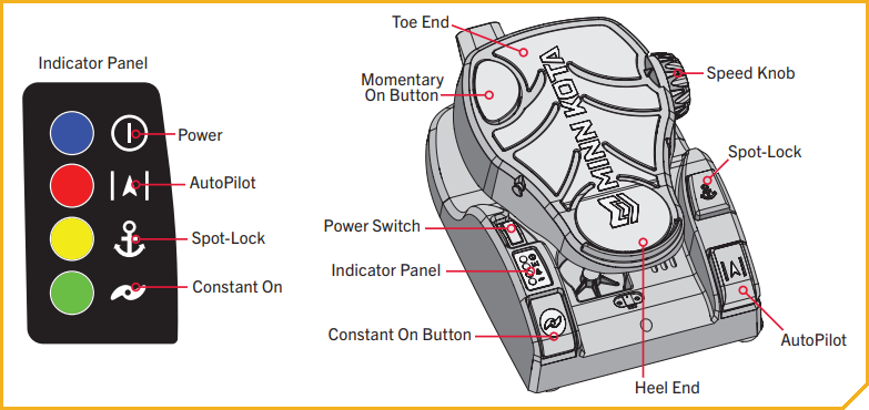
Ultrex Foot Pedal
-
Power
The Power Switch is located on the left-hand side of the foot pedal and is used to turn the power on and off. The blue light next to the Power icon on the Indicator Panel is illuminated when the power is on. Do not try to steer this motor with the foot pedal when it has lost power. -
Motor Speed
The Speed Knob is located on the top-right side of the Toe End of the foot pedal. Turn the Speed Knob clockwise to increase speed and counter-clockwise to decrease speed. Speed can also be adjusted using a Minn Kota-compatible remote. -
Momentary Motor Operation
In Momentary Motor Operation, the propeller will only run while downward force is applied to the Momentary On Button. The Momentary On Button is located on the top-left Toe End of the foot pedal. Applying downward pressure to the Momentary On Button will turn the propeller on. The motor will then run at the speed set by the Speed Knob. Removing downward force to the Momentary On Button will turn the propeller off. No indicator light is associated with the Momentary On Button. -
Constant Motor Operation
To switch to Constant Motor Operation, press the Constant On Button. The Constant On Button is located on the bottom-left Heel End of the foot pedal and is labeled on the foot pedal with a propeller symbol. In Constant mode, the propeller will continually run, regardless of whether or not force is being applied to the Momentary On Button. While in Constant Motor Operation, the propeller will run continuously at the speed set by the Speed Knob, or by a Minn Kota wireless remote. The green light next to the Constant On icon on the Indicator Panel will be lit when the motor is in Constant Motor Operation.
If the propeller is running and encounters an obstruction while in Momentary or Constant Mode, the increased electrical current generated by the obstruction will signal the motor to decrease power to the propeller to prevent damage. If the current overload is detected for more than 20 seconds, the prop will be disabled to prevent damage to the motor. In this event, the operator can turn the prop back on after ensuring that the obstruction has been cleared. -
Turn Left or Right
Push the Toe End of the foot pedal down to turn right and push the Heel End of the foot pedal down to turn left. The position and direction of the Steering Head directly corresponds to the position of the motor. When turning left or right, the steering motion will end when the cables controlling the direction of the Steering Head and Motor have come to the end of their range of motion. You must use your foot on the pedal to control the steering direction during manual operation.
The foot pedal is pressure sensitive. Applying gradual pressure to either the Toe or Heel End of the foot pedal will cause the direction to turn gradually. A higher amount of pressure will turn the unit more quickly in the engaged direction. The direction of the motor can also be controlled with a remote. Since the direction of the motor is controlled by pressure applied to the foot pedal and the reaction of the cables to that pressure, the motor will not turn straight without manually applying pressure to the foot pedal (or by using a remote) to align the cables to engage the motor to steer it straight. Due to the Steering Lock feature, the Steering Head and Motor will remain at the last steered position. Turning left or right can also be controlled by the Minn Kota micro remote. Refer to your remote manual to learn more. -
Steering in Reverse
The Control Head always indicates the direction of travel. To reverse the direction of travel, turn the Control Head in the complete opposite direction of its current location. Keep in mind that the steering motion will end when the cables controlling the direction of the Control Head have come to the end of their range of motion. -
Spot-Lock
The Spot-Lock button is located on the right side of the foot pedal and is labeled with an anchor symbol. When the Spot-Lock button is pressed, the location of the motor is recorded to memory. The yellow light next to the Spot-Lock icon on the Indicator Panel is illuminated when Spot-Lock is engaged. To engage Spot-Lock, press the Spot-Lock button. To disengage, press the Spot-Lock button again. When engaging Spot-Lock, a tone will be emitted. When disengaging Spot-Lock with the Spot-Lock button, no tone will be emitted. Steering the motor with the Foot Pedal or adjusting the speed using the Speed Knob will cancel Spot-Lock and a High-Low, High-Low, High-Low tone will be emitted. Spot-Lock can also be controlled with the remote. For more specific directions on how to use Spot-Lock, please refer to your remote manual. -
AutoPilot
The AutoPilot button is located on the bottom-right corner of the Foot Pedal and is indicated by the directional symbol. Pressing the AutoPilot button toggles the feature on and off. The red light next to the AutoPilot icon on the Indicator Panel is illuminated when this feature is engaged. When AutoPilot is engaged, a single tone is emitted. There is no tone emitted when AutoPilot is disengaged. AutoPilot can also be controlled using a compatible remote. For more specific directions on how to use AutoPilot, please refer to your remote manual. -
Steering Lock
When steering the Ultrex with either the foot pedal or a compatible Minn Kota remote, the Steering Lock feature will automatically lock the motor in the last position that was specified, allowing the operator to remove their foot from the pedal or hand from the remote and remain traveling in their chosen direction. The operator can set a new direction at any time by using the foot pedal or remote to rotate the motor. In the event that the motor encounters a solid obstruction, Steering Lock will rotate and lock the motor into a new position to prevent damage.
Remote Options
The Ultrex has 3 options for remotes shown below. The remote you have will determine how to use it. The Bluetooth Micro Remote is compatible with both i-Pilot Link and i-Pilot. Download the Quick Reference Guides for using the Ultrex with a Remote by clicking on the picture of your remote.
-
i-Pilot Link
-
i-Pilot
-
Bluetooth Micro Remote
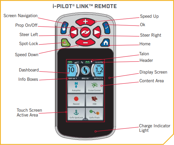
Using the i-Pilot Link Remote
-
Home
Press to bring up the Home Screen Buttons. -
Screen Navigation
Press to navigate the menu without touching the screen. Press and hold to lock and unlock the remote. -
Ok
Press to accept menu selections. Press to power remote on. Press and hold for 3 seconds to power remote off. -
Speed Up & Speed Down
Press to increase or decrease motor speed. -
Steer Left & Steer Right
Press to steer the motor to the left or to the right. -
Prop On/Off
Pressing this button will turn the Prop on and off. -
Spot-Lock
Press to enable and disable Spot-Lock.
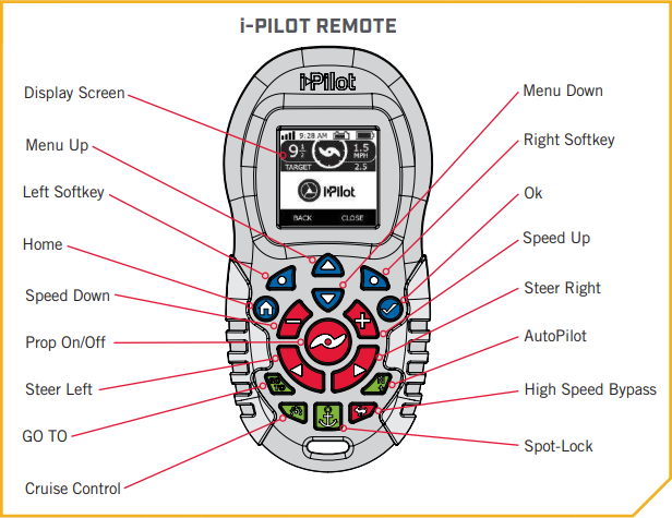
Using the i-Pilot Remote
-
Turning the prop on and off
When turning on the prop, the motor needs to be at least 18 inches below the mount. There is a lockout zone to prevent the motor from accidentally turning on and causing damage. Using the remote, the prop can be turned on and off by pressing the prop button. -
Increasing and Decreasing Speed
To increase or decrease your speed with the remote, the motor must be deployed and the prop on. Then press the + button to increase your speed and the - button to decrease your speed. -
Steering the Motor
To steer the motor left or right with the remote, the motor must be deployed. You can use the right arrow button to turn the motor to the right and the left arrow button to turn the motor to the left.
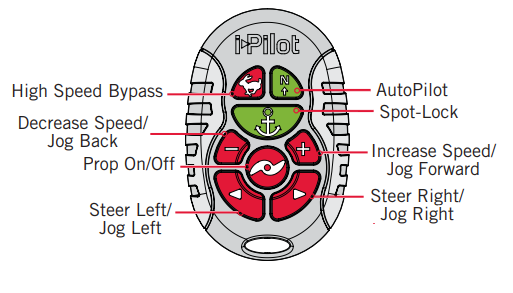
Using the Bluetooth Micro Remote
-
High Speed Bypass
Bypasses the current motor speed to speed 10. Double press to engage. Single press to disengage. -
Autopilot
Press to enable AutoPilot. The selection between Heading Lock and Course Lock must be made from either the fully functioning standard remote or the fish finder. -
Spot-Lock
Press to enable Spot-Lock. When Spot-Lock is enabled from the Micro Remote, use either the fully functioning standard remote or the fish finder if you want to save it. -
Increase Speed & Decrease Speed
Press to decrease or increase motor speed. -
Prop ON/OFF
This button is located in the middle of the remote. It turns the propeller on or off. Press the button once to turn the propeller ON; press button a second time to turn it OFF. The button does not need to be held down. -
Steer Left & Steer Right
These buttons are located to the right and left of the Prop ON/OFF button and have an arrow symbol. They cause the motor to turn in the desired direction as long as the button is held down. If the Steer Right or Steer Left button is held for more than seven seconds, the steering will automatically stop until the button is pressed again. -
Jog Back, Jog Forward, Jog Left, Jog Right
If your motor is Spot-Lock Jog enabled, the Speed Down (backwards), Speed Up (forward), Steer Right and Steer Left buttons function change to Jog the boat while in Spot-Lock. These buttons will then move your motor in 5' increments
Transducer and Ethernet Cable Routing Tips
Key times in the video:
- 0:00 Intro
- 0:22 Tools
- 1:19 Anchor upper end of Cables
- 1:56 Create a working Loop
- 2:33 Anchor cables at bottom of the Coil Cord
- 3:00 Direct Cables outboard of Coil Cord Cover and attach cables to Monoarm
- 4:06 Test Cable Position before tightening
- 4:30 Clean up Loose Cables and final tightening
- 4:55 Discuss final rigging
Foot Pedal Serial Number Location
- The serial number on the Ultrex, Fortrex, Maxxum and Edge foot controlled models is located on the inside edge of the foot pedal under the momentary switch.
Ultrex Long Mount Dimensions
Ultrex Short Mount Dimensions
Ultrex Foot Pedal Dimensions
Manuals
- Ultrex Manuals
-
Heading Sensor Manual
- Heading Sensor Instructions (for motors with i-Pilot or i-Pilot Link)
- i-Pilot Link Manuals and Compatibility Chart
- i-Pilot Manuals and Compatibility Chart
- Sonar Compatibility Charts